Walk Through Tutorial
Here's a quick example that shows how to use Nodi.
In this tutorial, we will look at basic usage of Nodi based on simple examples.
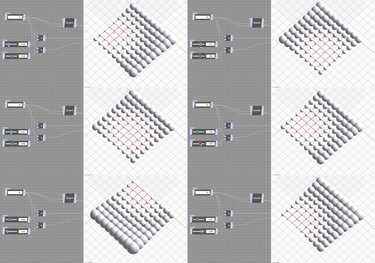
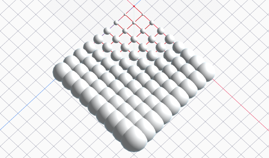
This example results in the following:
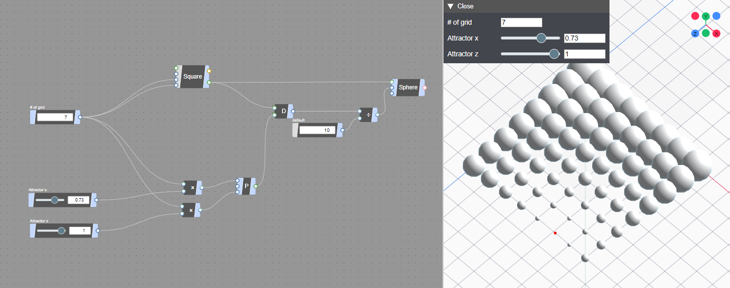
The size of the spheres arranged on the grid is changed according to the distance from a certain point. Here is the link for the final content. https://nodi3d.com/editor/aPLOH91sLtTCp8z0QrOU
Get started Nodi#
First, let's put a node that generates the grid.
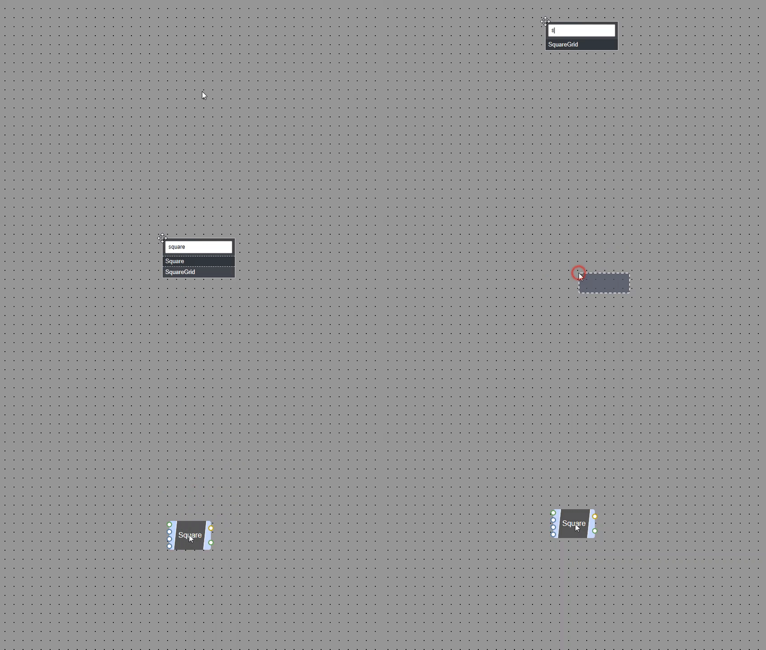
Display node search box by Tab or Double click on the Graph editor. (left side of app screen)
Enter SquareGrid in the form of the search box and select the candidate that appeared.
Then, the placeholder of the newly added node appears at the mouse position, and when you click in that state, the SquareGrid node is placed.
Each node has a different function. In Nodi, programming is performed by connecting these nodes to create a model.
Such programming techniques are called Node-based Programming or Dataflow programming. https://en.wikipedia.org/wiki/Visual_programming_language
Let's examine what functions the added SquareGrid node has. Press the right mouse button on a node to display the Node Inspector.
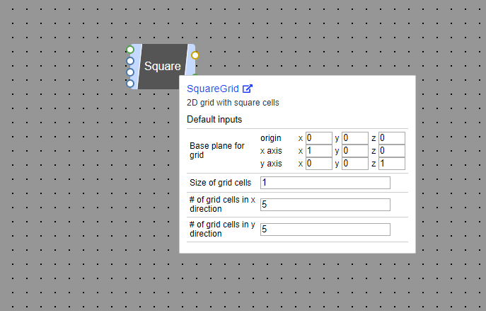
In the node inspector, you can check the description of the node and set the default value of the IO that the node has. If you look at the inspector, you can see that the SquareGrid node is the node that creates the square grid.
IO represents the entry and exit of the data used to join the nodes together. IO on the left side of each node is the data entry, and the right side is the data exit.
The default values of SquareGrid IO are following:
| Input | Default value |
|---|---|
| Base plane for grid | XY Plane |
| Size of grid cells in base plane | 1 |
| # of grid cells in x direction | 5 |
| # of grid cells in y direction | 5 |
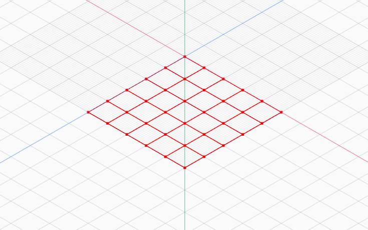
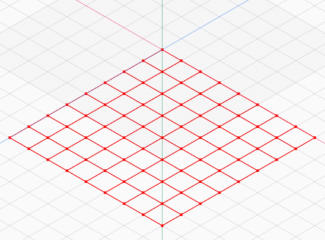
SquareGrid in the default state means that 5 grids of length 1 are laid vertically and horizontally on the XY plane. When you look at the Viewer (Right side of app screen), you can see that there is a grid laid out 5 by 5 in the vertical and horizontal directions, points that represent each vertex on the grid, and curves that represent each side of the grid are displayed.
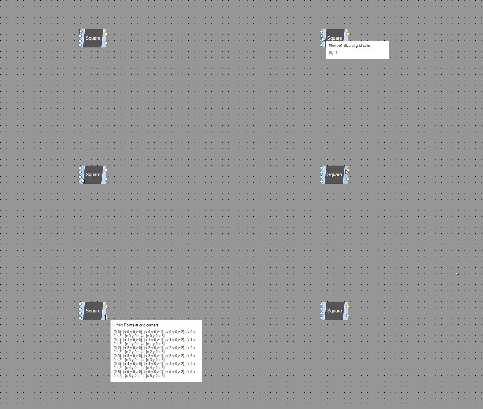
The data input to the node and the contents of the data output from the node can also be confirmed with the tooltip displayed by moving the mouse cursor over the IO.
Assemble the data flow#
Now that we know that a grid is created, let's change the number of grids. The number of grids in the SquareGrid node can be changed by the third and fourth inputs, which accept a Number type.
What is a data type ? Nodi has various data types, and the data types that are accepted differ depending on the IO of the node. Each IO has a data type, and will not accept input unless it has a matching type. https://docs.nodi3d.com/references/data-types
Add a UINumber node to specify the number of grids. Set the value of the UINumber node to 8 and connect the output of the UINumber node to the third and fourth inputs of the SquareGrid node. If you drag on IO, the edge will be displayed. By bringing the edge close to the IO you want to connect, connect the nodes.
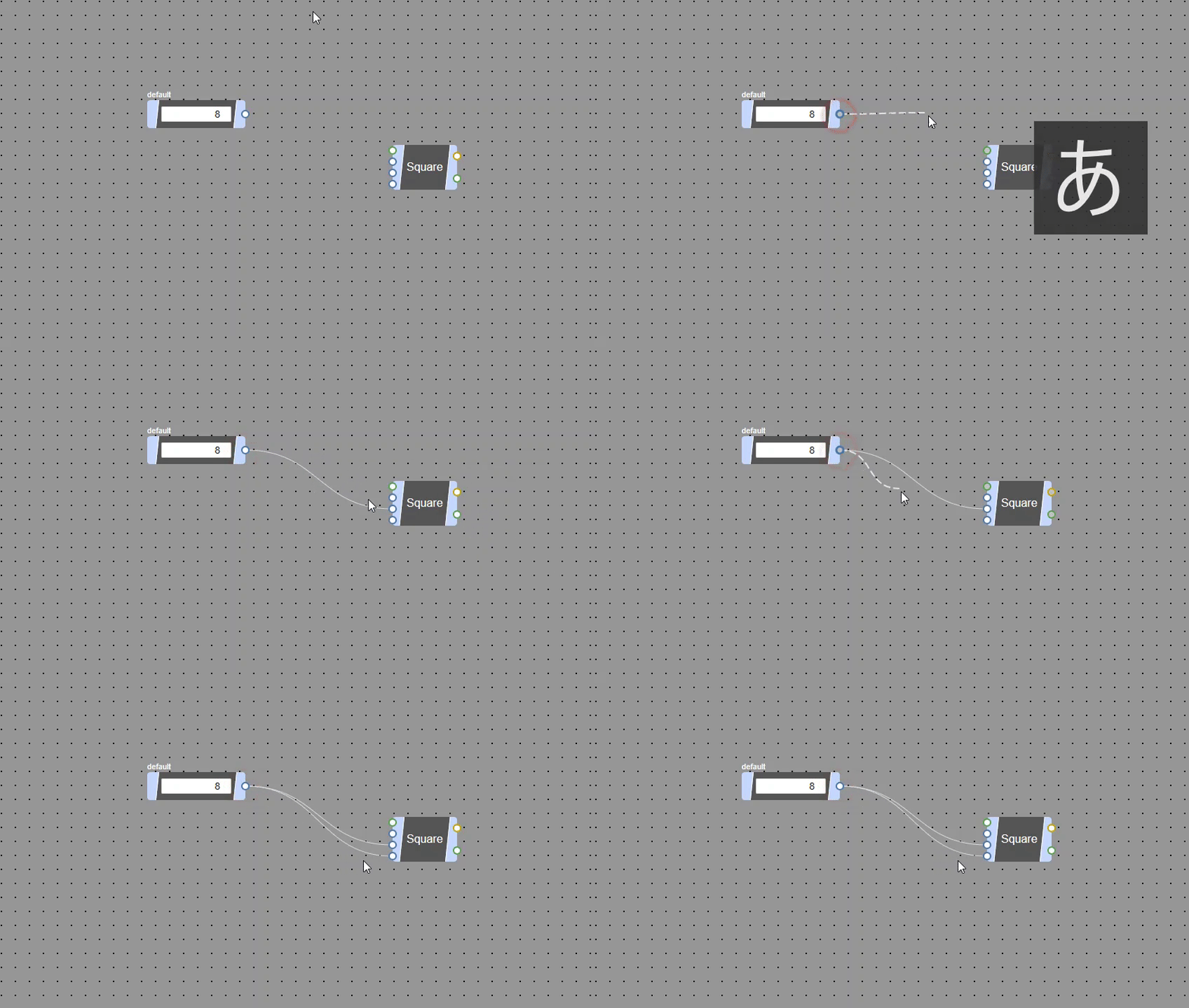
Connected edges can be disconnected using the IO inspector or the cut command. https://docs.nodi3d.com/basics/user-interfaces/data-flow#disconnect-edges
When connected, the number of vertical and horizontal grids output from SquareGrid is the number set in UINumber.
Arrange Spheres on the grid#
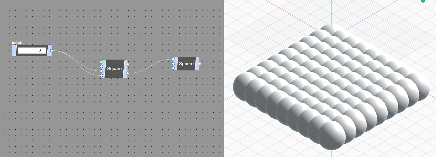
Next, place Sphere Mesh at the position of the point placed in SquareGrid. Add a Sphere node that generates Sphere Mesh.
A mesh is a collection of vertices, edges and faces that defines the shape of a polyhedral object in 3D computer graphics and solid modeling. https://en.wikipedia.org/wiki/Polygon_mesh
The Sphere node takes base position (Point, Vector) radius (Number) resolution (Number) as input. By connecting the Point output from SquareGrid to the input of this base position, Sphere can be placed at the position of that Point.
Create an Attractor#
Next, let's make the size of each Sphere change according to the distance from a certain Point (Attractor).
First, place a Point node to create a point that represents the Attractor. Point node outputs Point data at position (0, 0, 0) by default.
Measure the distance between each point of the grid output from SquareGrid and the Attractor.
Place a Distance node that measures the distance between two points, and connect the second output from SquareGrid to the first input of the Distance node.
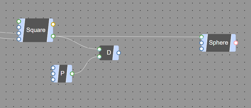
Then connect the Attractor's Point to the second input of the Distance node.
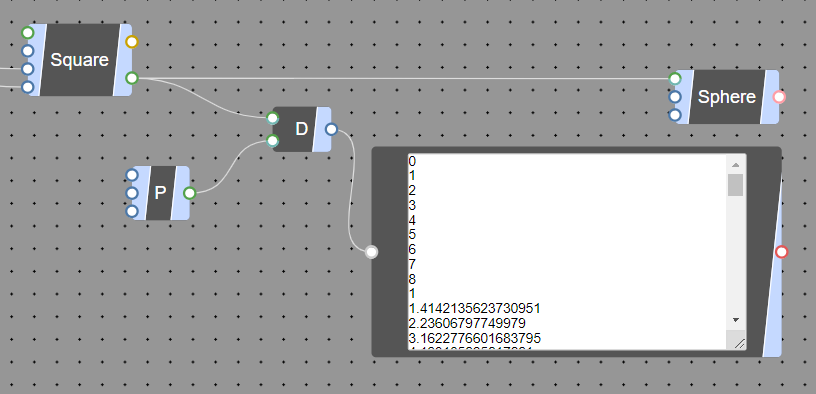
You have now measured the distance between each vertex of the grid and the Attractor. The data output from Distance can be previewed in the IO tooltip, but can also be confirmed by connecting a Text node.
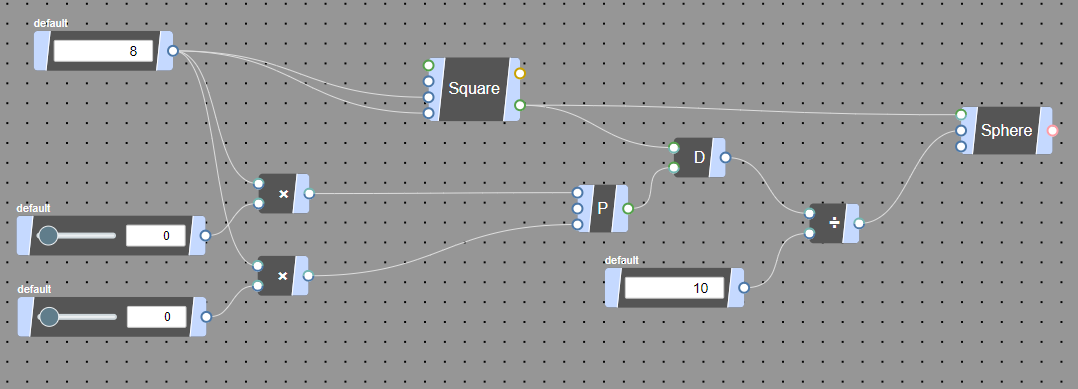
Next, divide the obtained distance by 10 by combining the Division node and the UINumber node, reduce the number, and connect it to the second input (radius) of Sphere.
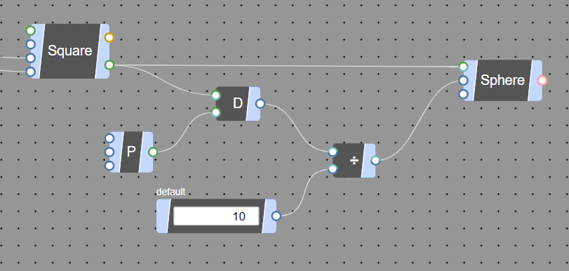
Then, the Sphere closer to the Attractor can be deformed to be smaller.
Let's control the position with the slider#
Next, let's make it possible to control the position of the attractor with the slider. Place two UINumberSlider nodes to change the X and Y positions of the attractor. Open the Inspector for each UINumberSlider and set the minimum value to 0 and the maximum value to 1.
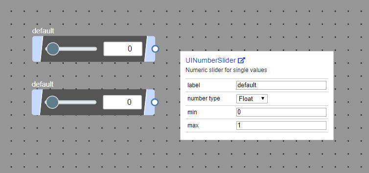
Then, multiply the output of UINumberSlider with the output of UINumber set to the grid size by the Multiplication node.
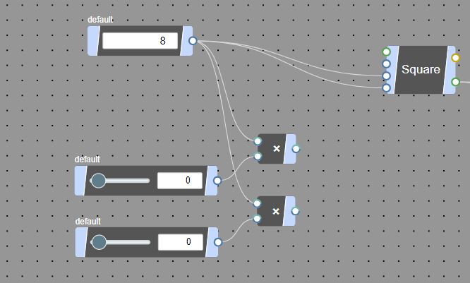
Then, when the result of the multiplication is connected to the X and Z inputs of the Point node representing the attractor, the position of the attractor will change according to the slider. This is completed! 👏
